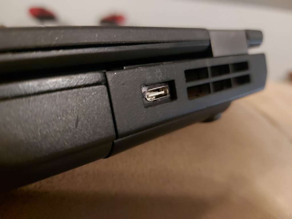
The Thinkpad T440P comes with the old Lenovo Slim USB charging port. In my experience, it has only been a source of annoyance as it seems every charger for it stops working after about six months. In this article, I will go through the process of converting the laptop to a USB C charging port. This is a decently well documented mod and is not very difficult to do with a little soldering.
The items required for this mod are a USB C PD trigger module, a soldering iron, a multimeter, and an approximately 500 Ohm resistor. The USB C PD trigger module just needs to provide 20V. This is the module that I happened to use:
Delinx 2PCs USB-C Type-C PD Trigger Module
Removing the Old Port
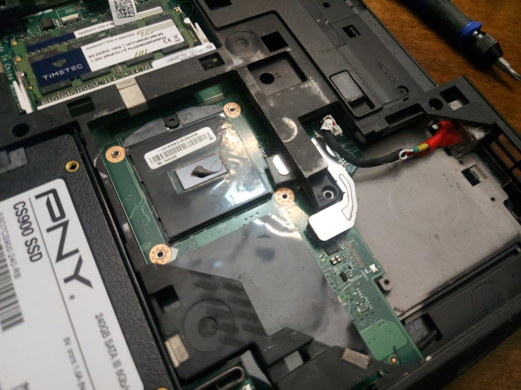
The first step is to remove the old Slim USB charging port. This requires removing the fan from off of the CPU to get access to the port.
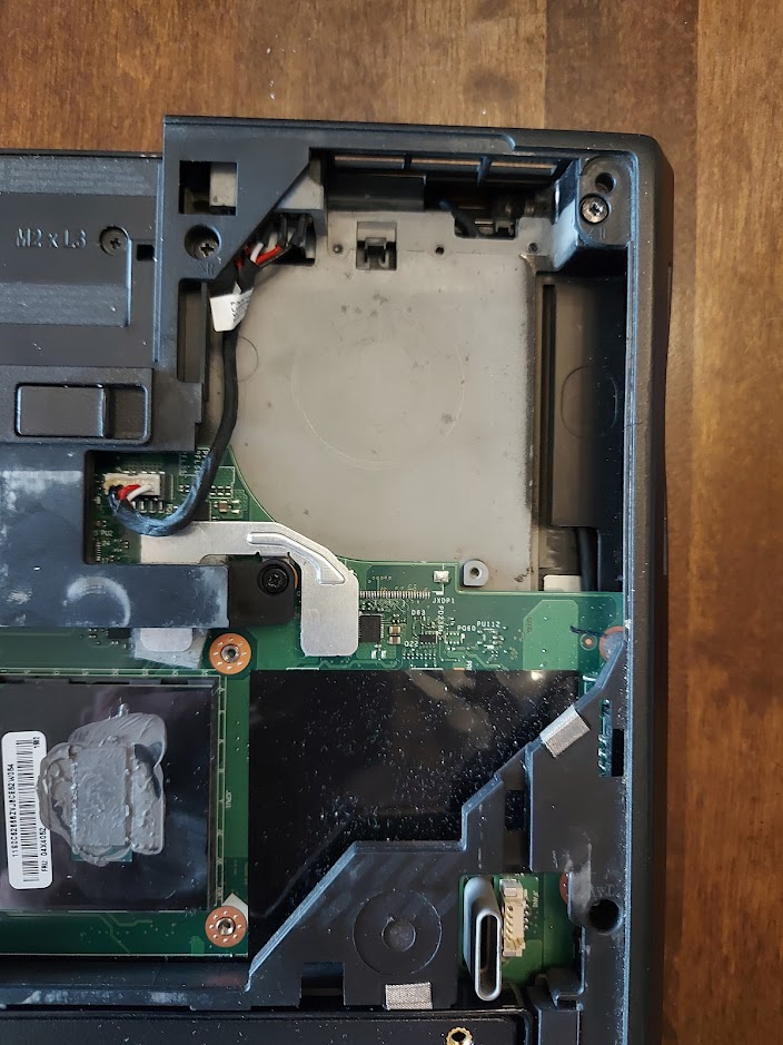
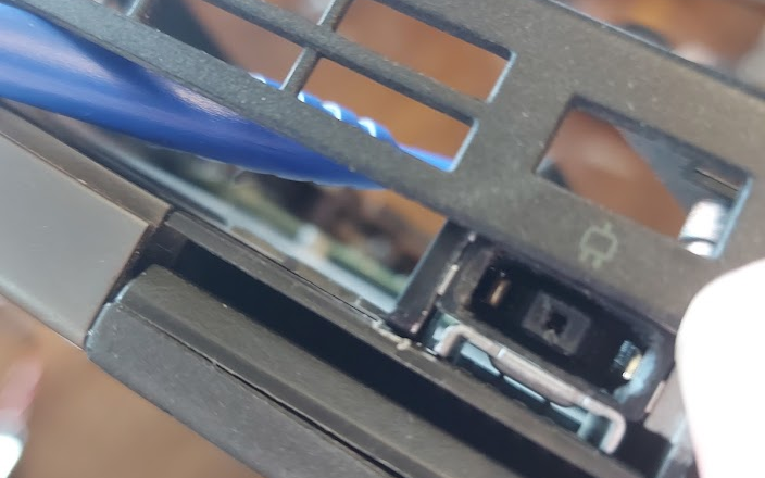
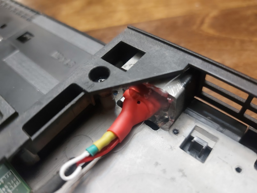
Since we have exposed the CPU and messed up the thermal paste, that will need to be reapplied later before the fan is put back on. There are tabs holding the old port into the encasing. Using a thin screwdriver to open up space between the old part and its holdings is the best way to wiggle it out. For me this was pretty difficult to do and involved a lot of gentling, yet violently smashing of the old port so that it would come out.
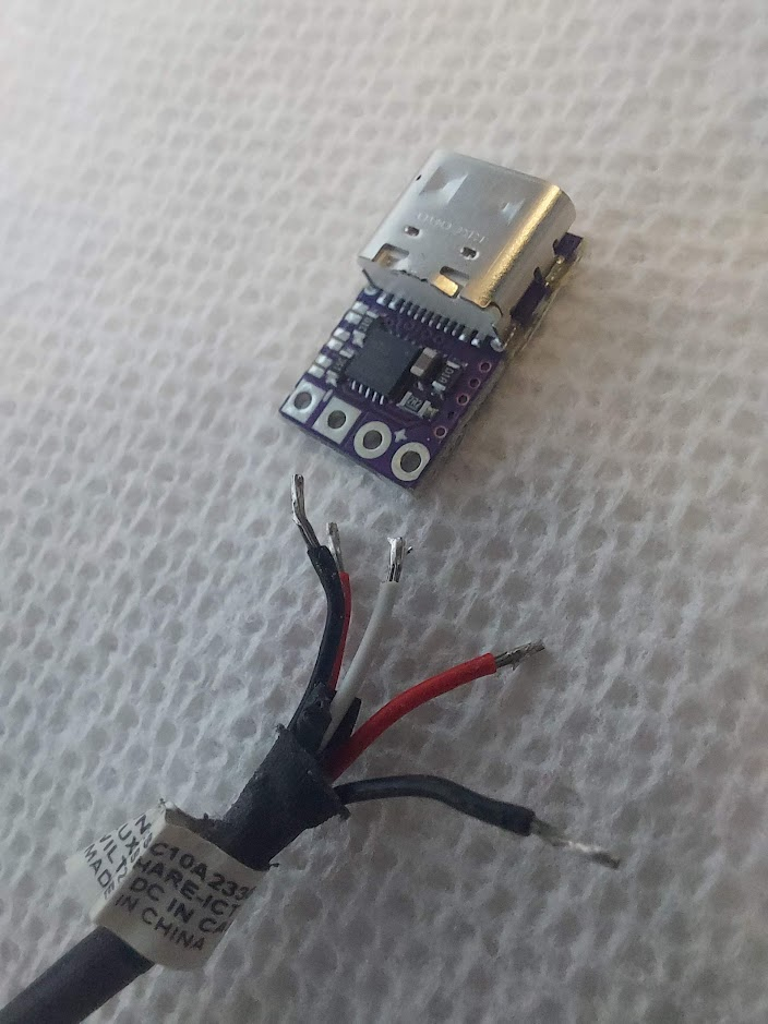
Once the old port is removed, we can salvage the cable from it to build the new USB C port.
The USB C Port
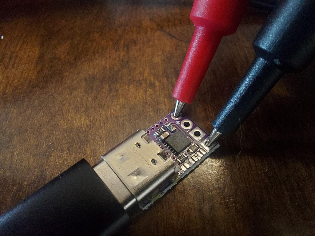
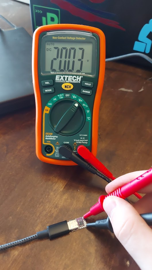
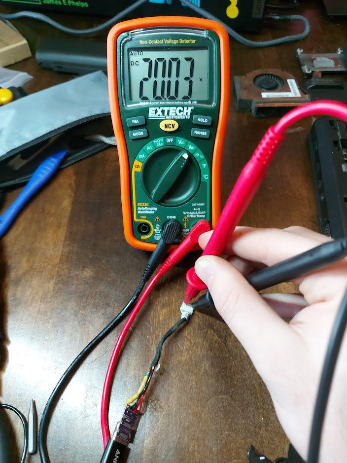
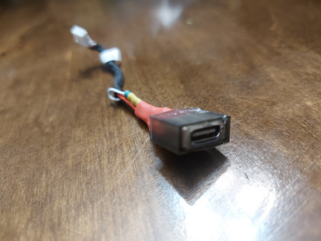
We can use a multimeter to test the output voltage of the USB C PD trigger module to insure that it is 20V.
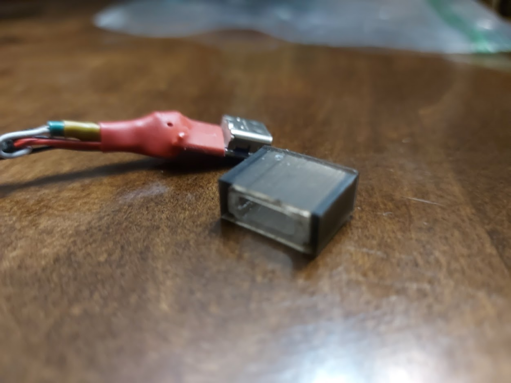
Once I was sure that the USB C Trigger module had the correct output, I desoldered the Slim USB port from its cables and separated them out.
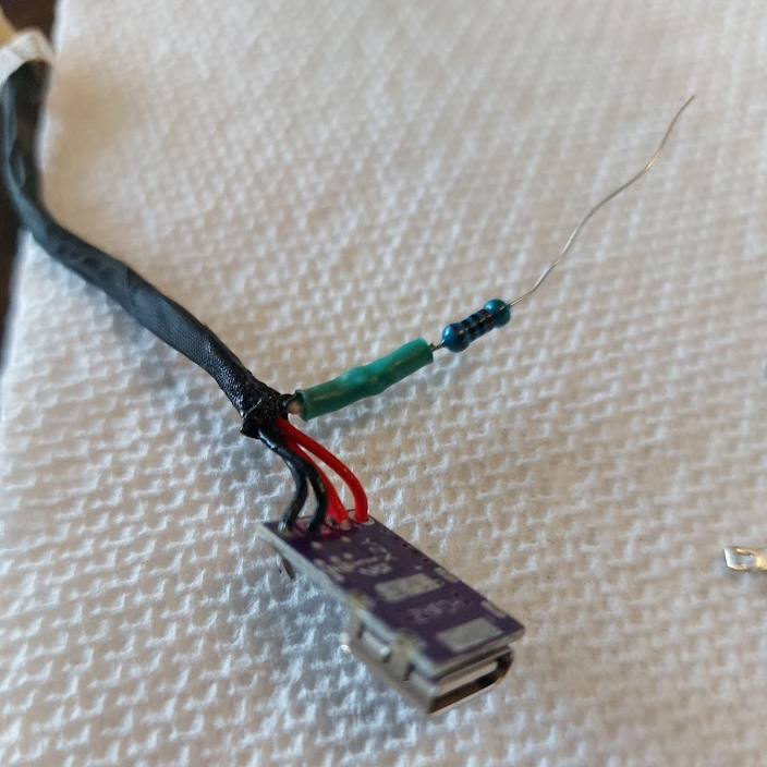
Next, I soldered the black cables to the negative side and the red cables to the positive side. The white cable is a sense wire for detecting the wattage for the computer. It needs to have a resistor attached and then it can be soldered to the negative side with the black cables. The resistor should be around 500 Ohm, it doesn’t need to be exact to work correctly.
Finally, I double checked to make sure that on the end that goes into the motherboard, we were still getting 20V.
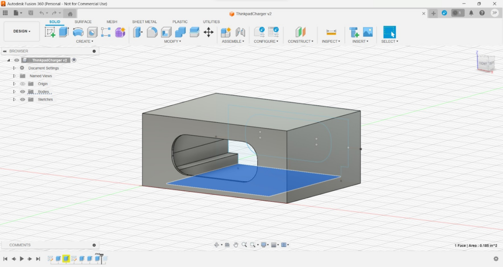
A New Port Housing
Using a dial caliper, I measured out the dimensions of the hole for the port and the module and designed a new port housing using Fusion 360. If you dual boot like me, make sure to have your time set correctly in your OS for Fusion 360 or it will never load and never tell you why.
It was during the holidays when I did this, so all of the libraries and universities around me with 3D printers were closed. I opted to use a 3D printing service online which ended up taking over a month to print and then ship my part to me.
I put the port inside the housing using hot glue. The hot glue worked okay, but I would have preferred something a little bit stronger.
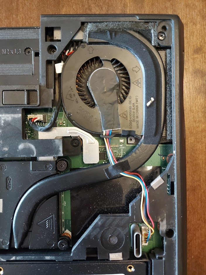
Putting it all together
I slid the port into the laptop and then filled up the back with hot glue to hold it in. Again, the hot glue doesn’t feel super sturdy, but it has held it in so far.
Lastly, I cleaned up and reapplied the thermal paste before putting the fan back onto the CPU.
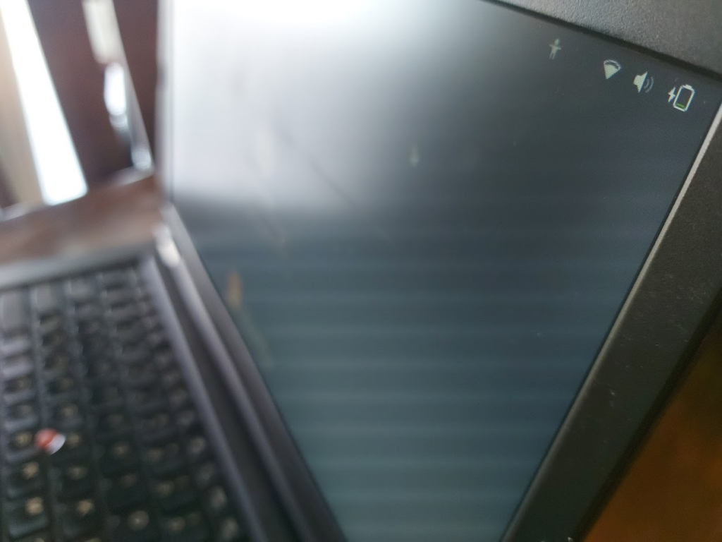
In the end it worked and the port does not look terrible. It was a little bit of a squeeze to move the cable over so the fan could go back in. Might be a good idea to make sure the back of the port is not too rigid. If I could do it again, I would probably find an alternative solution to hot glue for holding it in. In theory, this is supposed to go with a 90W charger, but if the laptop is off it will slowly charge alright with a lower wattage.