
In this series of articles I will be going over my efforts to create a home media control system using a couple ESP8266’s. The end result will be a fully automated theater setup through Amazon Alexa and a webapp built in Angular. This series will go over setting up an ESP8266 to read and transmit both IR signal and RF signals, making controllable smart devices for Alexa, creating a locally hosted webapp for remote control, and the steps to properly configure a home network.
The following video shows the end result using Alexa to turn on all devices in the home theater. This setup includes a video streaming box, surround system, projector, radio-controlled projector screen, and an electric fireplace. The specific device information is listed under the video.
Supplies
- HiLetGo ESP8266
- Tiny Premium Breadboard
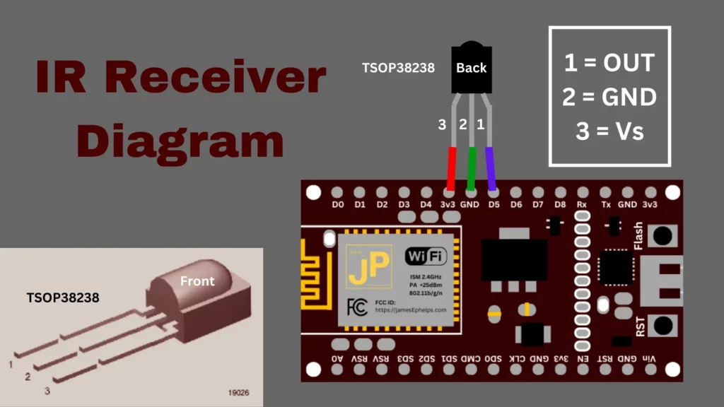
- IR (Infrared) Receiver Sensor – TSOP38238
- Super-bright 5mm IR LED – 940nm
- kwmobile 433 MHz Transmitter and Receiver Module Kit
For this project, I will be using Nodemcu ESP8266 Development Boards that I purchased off of Amazon. These can be found for cheaper from websites that ship from China, but I was on a time limit since I will be returning back to school soon, so I went the faster Amazon route. I specifically used the HiLetGo models which seemed to work. Of the three I bought, one arrived dead, but the other two were fine.
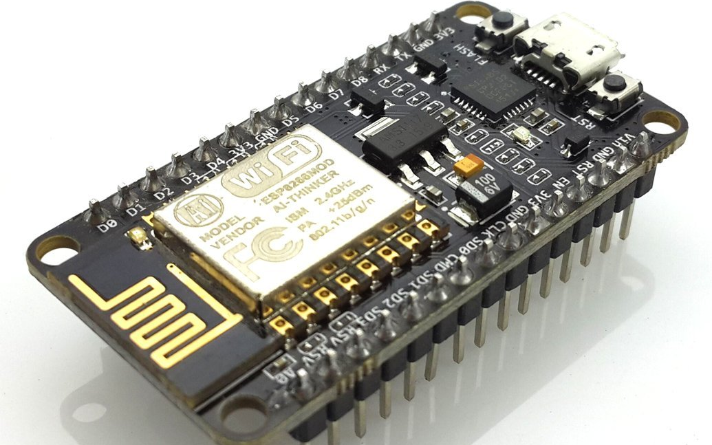
The ESP8266 is a microcontroller that can be easily programmed through a micro usb connection using an IDE like Arduino. The ESP8266 is special because it has wifi capabilities and a very strong community behind it, making resources for it readily available on the internet.
In addition to the boards, I also purchased an IR Receiver and LED from Adafruit. These will allow us to read Infrared signals from the remotes and then be able to replicate them ourselves on our ESP8266 to emit the same signals as our remotes. I also got a tiny breadboard from Adafruit to allow for easier prototyping before I permanently soldered components to the ESP8266’s.
Lastly, I also ended up needing to get a 433 MHz RF receiver and transmitter for the projector screen. The projector screen is controlled by an RF remote which emits radio signals. When searching for such a receiver and transmitter, I found many transmitters that seemed to be missing a coil on Amazon as shown below.
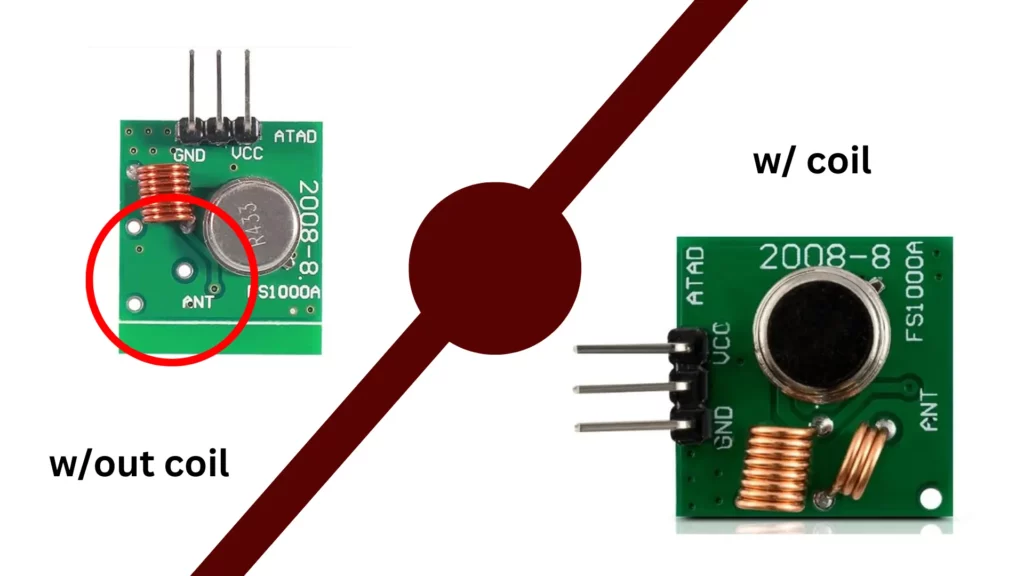
What effect this has is outside of the scope of my knowledge, but several reviewers indicated the coil is necessary for proper functioning, so I was sure to buy one with the coil. For me, all the product listings when I first searched on Amazon were missing this coil. I had to search for a while before I found one that seemed to actually have the coil.
Receiving IR Signals
Most devices are controlled using IR remotes which emit an IR signal that the device can pick up on using a receiver. To get our needed signals, we will connect the IR receiver to our ESP8266 board and then record data that it picks up from our remotes. We will use a library called IRremoteESP8266 that can be found in the Arduino libraries to understand the data that the receiver picks up.
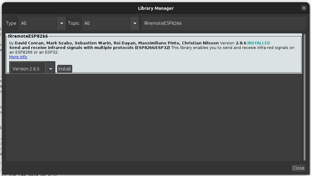
In Arduino, go to Tools>Manage Libraries… (Ctrl+shift+I). Search for “IRremoteESP8266” and install the only one that pops up.
Now go to your file manager and find where Arduino is installed. From there go to libraries/IRremoteESP8266/examples/IRrecDumpv2 and open in Arduino the IRrecDumpv2.ino file.
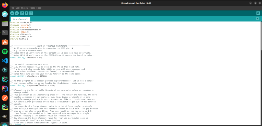
This sketch allows us to receive codes from the remotes on the ESP8266. The top section has a couple of parameters you can edit to fine tune your setup. It is likely you will not need to modify this at all. For mine to work, I had to change kMinUnknownSize to a very high number, because I was picking up random numbers on my receiver.
Deploy this sketch to your ESP8266 by pressing the arrow up in the top left. This will pop up a terminal, displaying the status of the compiling process and then the write process. Now we need to actually connect the IR receiver to our ESP8266.
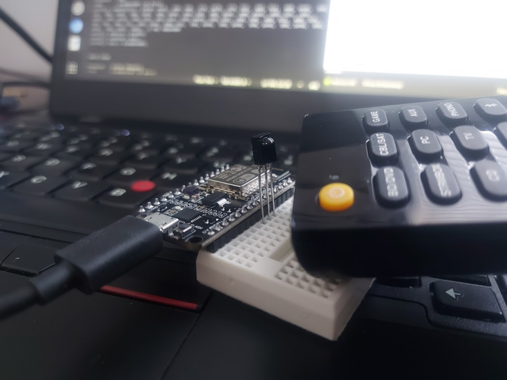
I was able to use the breadboard and just plug the receiver in since this is a super simple setup. Once the receiver is connected, keep the board connected to the computer, and open the serial monitor in Arduino.
If successful, each time you press a button, output should show up in the serial monitor that looks like this:
Timestamp : 000740.274
Library   : v2.8.6

Protocol  : NEC
Code      : 0x10EF8877 (32 Bits)
uint16_t rawData[71] = {9078, 4478,  598, 560,  574, 558,  574, 558,  574, 1686,  572, 560,  572, 562,  572, 558,  574, 558,  576, 1686,  570, 1692,  576, 1686,  570, 562,  572, 1690,  576, 1686,  572, 1690,  576, 1684,  572, 1690,  578, 554,  568, 564,  570, 562,  572, 1690,  576, 556,  576, 554,  580, 554,  568, 564,  570, 1694,  574, 1686,  570, 1692,  576, 556,  576, 1686,  572, 1692,  576, 1686,  570, 39392,  9082, 2240,  600};  // NEC 10EF8877
uint32_t address = 0x8;
uint32_t command = 0x11;
uint64_t data = 0x10EF8877;
Go through each button on the remote that you want and record what it outputs to the serial monitor. We will use the code (ex. 0x10EF8877), the protocol (ex. NEC), and the amount of bits (ex. 32 Bits) when we send a signal to the remote. Later when we write the code to send the signals it will be done similar to this this:
// NEC Protocol
irsend.sendNEC(0x10EF8877, 32, 2);
// Epson Protocol
irsend.sendEpson(0x4BB641BE, 32, 2);
I keep getting code 0xFFFFFF in the serial monitor
In the NEC protocol, 0xFFFFFF is the repeat command and simply means that whatever the last command sent by the remote is needs to be repeated. Just ignore these and keep sending signals with the remote until you get a code that is not 0xFFFFFF
I am only getting question marks in the serial monitor
Make sure that your baudrate in the serial monitor is set to the same as was set in the above sketch (probably 115200). If the baudrate does not match, you might just get a bunch of question marks in the serial monitor.
I am just getting continuous random output in the serial monitor
Check to make sure that the wiring is correct. If it is and the problem persists, try setting the kMinUnknownSize variable in the sketch to 10000 and re-deploy the sketch to your esp8266.
Sending IR Signals
To send the signals that we recorded, we must first wire the IR Led up to our ESP8266. The following diagram shows the proper way to connect the Led to the board.
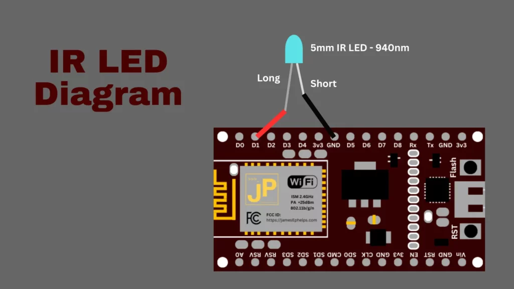
This should be pretty easy using a breadboard and some wires. To test if your remote signals work, navigate back to your Arduino folder like previously and go through the folders: libraries/IRremoteESP8266/examples/IRsendDemo and open the IRsendDemo.ino file. If you followed the diagram above, you will need to change kIrLed variable to 5. Now, put your own codes in the loop() so that your ESP8266 will continuously send your signals so we can test them. Deploy this new sketch to your board.
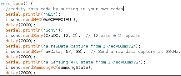
If you want to check if your board is sending any IR signals at all, you can look at the IR led through your phone’s camera. If it is working, you will see distinct purple flashes. If you have the correct codes, it will now be able to interact with your controllable devices just like your original remote does.
Receiving RF signals
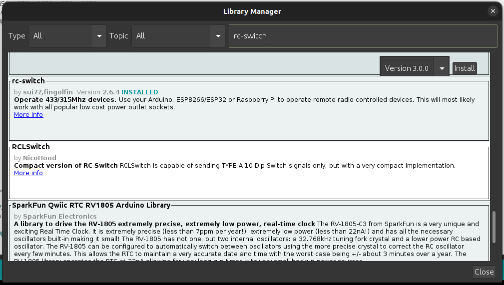
If you have a device that is radio controlled by 433MHz, we can use the rc-switch library to decode and transmit radio signals. Go back to the library manager (Ctrl+shift+I) in Arduino and search for rc-switch to install. Make sure to install the one by sui77 and fingolfin.
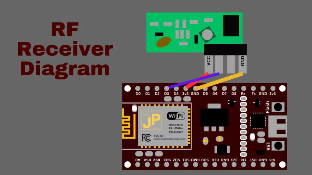
Next, go to the Arduino folder and navigate through the following folders libraries/rc-switch/examples/ReceiveDemo_Simple/ and open ReceiveDemo_Simple.ino. This sketch allows us to use the RF receiver to get codes that represent the radio signals from our RF remotes. Deploy this sketch to the board. (You may need to adjust the baudrate if you are using a different rate. This is done in the code at Serial.begin(9600) where 9600 is the baudrate) Now, wire up the receiver as shown in this diagram.
If done correctly, you should now be able to press buttons on your RF remote and data will show up in the Serial Monitor. There are three things we’re are looking for: a code, a number of bits, and a protocol number.
6582737
24bit
Protocol: 1
Transmitting RF Signals
To test if the RF signals we picked up work, we can use the provided SendDemo.ino file in the folders Arduino/libraries/rc-switch/examples/SendDemo/. If you got the output from the previous example, you would test it by adding a line of code to the loop() function like so:
void loop() {
  mySwitch.send(6582737, 24);
  delay(1000);
}
The wiring for the transmitter is done as follows:
If you are using this same setup, you will need to change the line in the sketch mySwitch.enableTransmit(4); so that it uses pin 4 which is D2. Deploy the sketch and you should now be able to control your RF device using the ESP8266.
In summary, following these steps, you should be able to get all the data from your remotes and devices that you will need in order to control them. In part 2, we will go over actually doing the programming so that voice assistants like Alexa or a custom webapp can send these signals to the devices.